
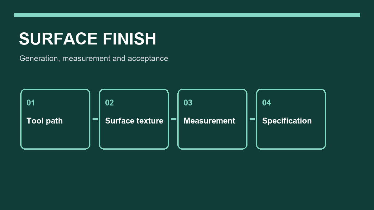
A milled surface can look smooth and still miss a functional requirement. It can also look visibly marked while meeting the specified roughness parameter. The reason is simple: a surface is made by a cutting process, then summarized by a measurement method. Those are related steps, but they are not interchangeable.
Start with the function#
Before choosing a finishing pass, identify what the surface must do. A sealing face, sliding fit and cosmetic enclosure do not need the same texture description. A single Ra value may be useful, but it does not describe every peak, valley or direction in a profile. NIST's calibration overview lists Ra, Rq, Rz and other distinct parameters and discusses uncertainty for their measurement.
Write the parameter and acceptance method into the drawing or inspection plan. If direction matters, state the lay or the direction of measurement. Avoid treating a visual impression as a substitute for an agreed measurement.
How milling leaves its signature#
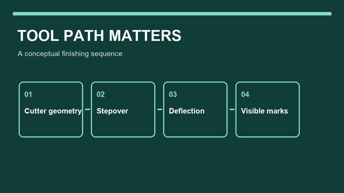
Cutter geometry, stepover and stability influence the resulting milling marks.
Tool geometry, step-over, feed, engagement and machine stability shape the surface. Sandvik Coromant's profile-milling guidance discusses contouring paths, scallop height and the value of limiting abrupt workload changes. That is supplier guidance for selecting a process, not a universal guarantee of a finish.
Consider three patterns during a trial:
- Regular cusps: Review cutter shape and step-over before changing unrelated parameters.
- Directional streaks: Check path direction, runout and how the surface is being viewed or measured.
- Irregular waves: Investigate vibration, tool overhang, fixturing and engagement changes.
These are diagnostic prompts, not proof of a single root cause. Inspect the tool, machine setup and measured profile before changing the process.
Measure the surface you specified#
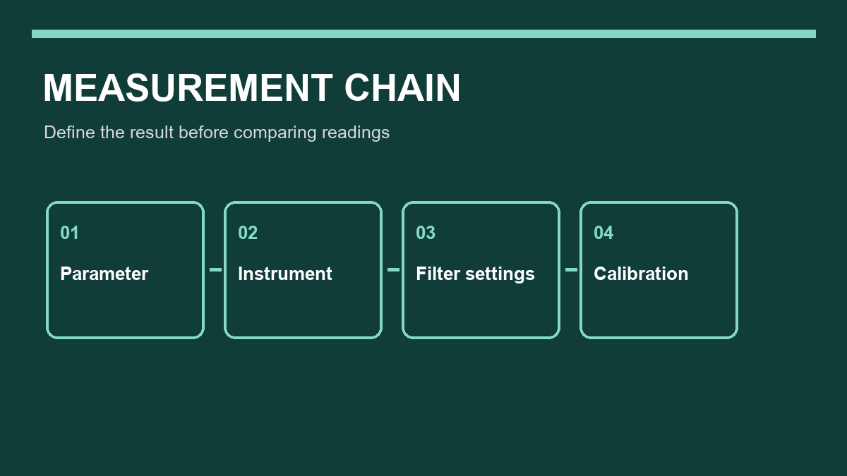
Comparable surface readings require a defined parameter and consistent measurement settings.
The reported number depends on the measurement chain. Instrument, stylus geometry or optical method, sampling direction and filter settings can change which features enter the result. NIST's surface-finish metrology introduction compares stylus and optical approaches; its calibration work explains why measurement conditions and uncertainty matter. Historical NIST publications remain useful technical references, but they are not new 2026 findings.
For repeatable inspection, record:
- The required parameter and the surface area to evaluate.
- Measurement direction and instrument type.
- Filter and sampling settings used by the laboratory.
- Calibration or check-standard status and any relevant uncertainty.
If two readings disagree, first confirm that the two methods evaluated the same region under comparable conditions. A machining adjustment is premature when the disagreement comes from the measurement setup.
A practical acceptance loop#
Make a sample, measure it using the agreed method, and compare both the number and the functional surface behavior with the requirement. Then change one process variable at a time and repeat the check. This keeps the discussion anchored to the part rather than an attractive surface photograph or an isolated roughness number.