
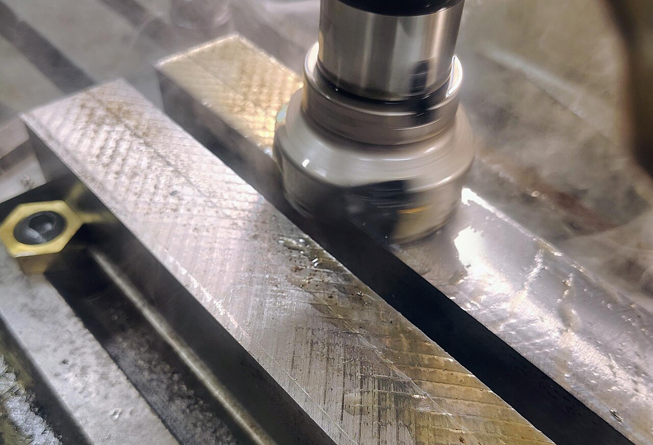
A face-milled part can meet its dimensional target and still carry a burr on the exit edge. That burr may interfere with assembly, handling or later inspection. The useful question is not simply how to remove it. It is where the cutter exits the workpiece, why that edge is vulnerable and whether the process can avoid creating the difficult burr in the first place.
Start at the exit edge#
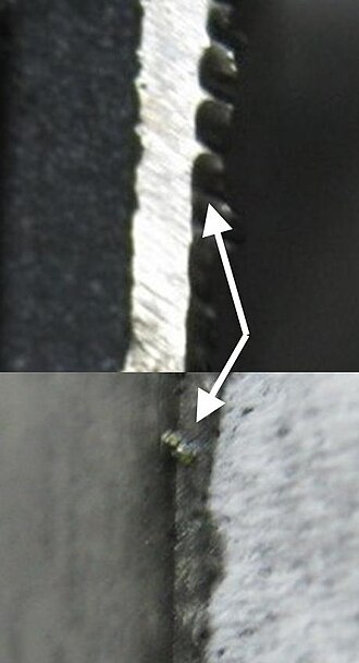
An exit burr is associated with a cutting edge leaving the workpiece while removing material. In a planar-milling study archived by UC Berkeley, researchers explored paths designed to avoid such tool exits and reported better edge quality in the studied cases. This does not mean every production contour can be made exit-free; geometry, access and tool engagement constrain the path.
The edge's location matters as much as its size. A NIST process-planning paper notes that a milling direction which seems inconsequential to the machining cell can place an exit burr where later deburring is harder. Plan the edge condition with assembly and finishing in view, rather than treating deburring as an isolated afterthought.
Why one tool-path fix is not universal#
Exit angle and tool geometry change the kind of burr a process produces. A face-milling study by Olvera and Barrow investigated medium-carbon steel under finishing and roughing conditions. It found that exit angle and tool nose geometry influenced the exit burr. Its specific findings belong to those tested conditions; they should not be copied as a setpoint for another alloy, cutter or depth of cut.
The practical implication is to review the exit geometry before prescribing a tool change. If a burr appears only on one outer edge, map the cutter's direction and engagement at that boundary. If it appears around multiple features, look for repeated exit events in the programmed path. Tool wear, material behavior and fixture stability may also influence the result. A photograph cannot separate those causes.
A controlled check on the shop floor#
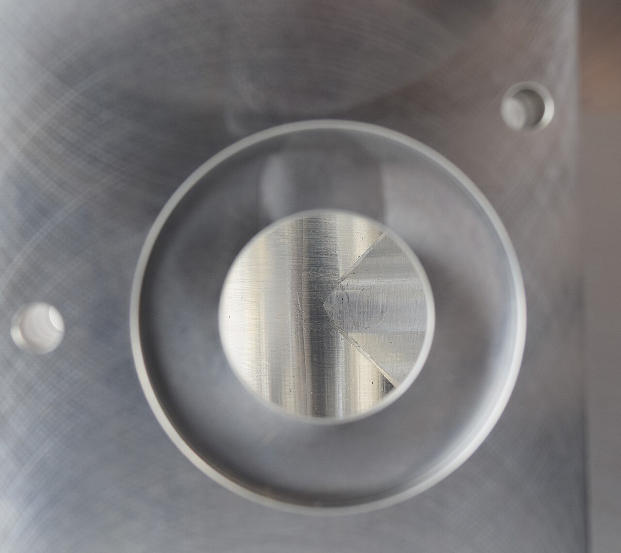
- Mark the functional edge. Identify which edge is touched, assembled, sealed or inspected. State the acceptable condition in the drawing or work instruction.
- Map cutter entry and exit. Review the CAM path at each critical boundary, including finishing passes and local re-entries.
- Inspect before deburring. Record the location and character of the burr while the machining cause is still visible.
- Change one variable. Trial a revised path, cutter geometry or engagement strategy without changing everything at once.
- Verify the whole part. Confirm that a better edge did not create a poor finish, longer cycle or new burr elsewhere.
When a path revision is impractical, specify a removal method and a post-deburr inspection step. The goal is a controlled edge, not a promise of a universally burr-free cut. Historical research provides the mechanism; the current part trial establishes whether the proposed change works in that shop.